- 您现在的位置:买卖IC网 > Sheet目录528 > TRM-900-NT (Linx Technologies Inc)RF TXRX 915MHZ NT SERIES
�� �
�
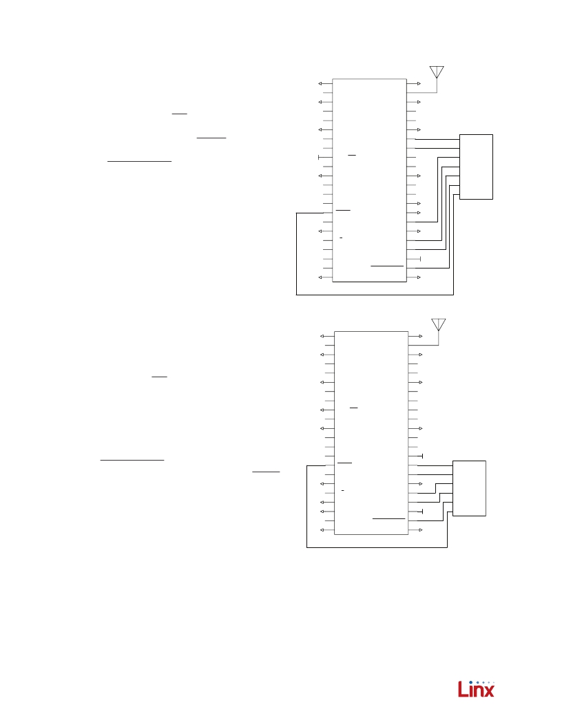
�Typical� Applications�
�Figures� 11� and� 12� show� two� circuits� using� the� CDI.�
�Circuit� A� shows� the� transceiver� set� up� for� transparent�
�data� operation.� The� TRPT/PKT� line� is� pulled� high,�
�GND�
�GND�
�1�
�2�
�3�
�4�
�5�
�GND�
�NC�
�GND�
�NC�
�NC�
�GND�
�ANTENNA�
�GND�
�NC�
�NC�
�44�
�43�
�42�
�41�
�40�
�GND�
�GND�
�GND�
�GND�
�1�
�2�
�3�
�4�
�5�
�GND�
�NC�
�GND�
�NC�
�NC�
�placing� the� module� into� Transparent� Mode.�
�The� microcontroller� monitors� the� READY� line� for� flow�
�control� and� to� monitor� the� status� of� the� module.�
�It� controls� POWER_DOWN� and� STANDBY� for� power�
�conservation,� though� these� could� be� hardwired� if� power�
�conservation� is� not� necessary� for� the� application.�
�GND�
�VCC�
�6�
�7�
�8�
�9�
�10�
�11�
�12�
�13�
�GND�
�NC�
�NC�
�TRPT/PKT�
�CHN_SEL� 0�
�GND�
�CHN_SEL� 1�
�CHN_SEL� 2�
�GND�
�DATA_IN�
�DATA_OUT�
�NC�
�NC�
�GND�
�NC�
�NC�
�39�
�38�
�37�
�36�
�35�
�34�
�33�
�32�
�GND�
�GND�
�GPIO�
�GPIO�
�RX�
�TX�
�GPIO�
�GPIO�
�GPIO�
�μ�
�GND�
�GND�
�6�
�7�
�8�
�9�
�10�
�11�
�12�
�13�
�GND�
�NC�
�NC�
�TRPT/P�
�CHN_S�
�GND�
�CHN_S�
�CHN_S�
�CMD_DATA_IN� and� CMD_DATA_OUT� are� connected� to�
�14�
�LVL_ADJ�
�CMD_DATA� _BAUD�
�31�
�GND�
�14�
�LVL_AD�
�the� TX� and� RX� lines� of� the� UART� in� the� microcontroller.�
�CMD_DATA_TYPE� is� hardwired� low� for� command� data.�
�CMD_DATA_BAUD� is� hardwired� to� the� low� data� rate�
�GND�
�15�
�16�
�17�
�18�
�READY�
�NC�
�GND�
�T/R_SEL�
�CMD_DATA� _TYPE�
�CMD_DATA� _OUT�
�GND�
�CMD_DATA� _IN�
�30�
�29�
�28�
�27�
�GND�
�GND�
�GND�
�15�
�16�
�17�
�18�
�READY�
�NC�
�GND�
�T/R_SE�
�(9,600bps).� DATA_IN� and� DATA_OUT� are� connected� to�
�GPIOs� on� a� microcontroller� that� generates� and� decodes�
�the� over-the-air� data.�
�GND�
�19�
�20�
�21�
�22�
�BAUD0�
�BAUD1�
�RSSI�
�GND�
�STANDBY�
�VCC�
�POWER_DOWN�
�GND�
�26�
�25�
�24�
�23�
�VCC�
�GND�
�GND�
�GND�
�GND�
�19�
�20�
�21�
�22�
�BAUD0�
�BAUD1�
�RSSI�
�GND�
�The� channel,� power� level,� transmit� /� receive� state�
�and� baud� band� are� controlled� by� the� microcontroller�
�through� the� CDI� rather� than� by� the� hardware� lines.�
�Figure� 11:� NT� Series� Transceiver� Typical� Application� Circuits�
�The� microcontroller� also� reads� the� 44� RSSI� level� through�
�GND�
�GND�
�GND�
�1�
�GND�
�1�
�GND�
�GND�
�44�
�GND�
�the� CDI.�
�GND�
�2�
�3�
�NC�
�GND�
�ANTENNA�
�GND�
�43�
�42�
�GND�
�GND�
�2�
�3�
�NC�
�GND�
�ANTENNA�
�GND�
�43�
�42�
�GND�
�NC�
�NC�
�Circuit� B� shows� NC� the� transceiver� NC� set� 40� up� for� packet�
�4 41�
�5�
�4�
�5�
�NC�
�NC�
�NC�
�NC�
�41�
�40�
�operation.� The� TRPT/PKT� line� GND� pulled� low,� placing� the�
�GND�
�module� into� Packet� Mode.� CMD_DATA_IN� and� GPIO�
�NC�
�DATA_IN�
�GPIO�
�NC�
�DATA_OUT�
�μ�
�of� the� UART� in� CHN_SEL� microcontroller.� The� microcontroller�
�TX�
�NC�
�controls� the� 12� CMD_DATA_TYPE� GND� line� 33� to� GND� toggle� between�
�GND�
�GPIO�
�Command� Data� CHN_SEL� changing� the� module’s� settings� and�
�for� 2�
�NC�
�GPIO�
�Packet� Data� for� transmission� _BAUD� reception.� It� also�
�GND�
�6�
�7� 38�
�8� 37�
�9 36VCC TRPT/PKT NC�
�CMD_DATA_OUT� are� connected� to� the� TX� and� RX� lines�
�10� 35�
�11� 34�
�CHN_SEL� 1� NC� GPIO�
�13� 32�
�14� 31�
�GND�
�GND�
�6�
�7�
�8�
�9�
�10�
�11�
�12�
�13�
�14�
�GND�
�NC�
�NC�
�TRPT/PKT�
�CHN_SEL� 0�
�GND�
�CHN_SEL� 1�
�CHN_SEL� 2�
�LVL_ADJ�
�GND�
�DATA_IN�
�DATA_OUT�
�NC�
�NC�
�GND�
�NC�
�NC�
�CMD_DATA� _BAUD�
�39�
�38�
�37�
�36�
�35�
�34�
�33�
�32�
�31�
�GND�
�GND�
�VCC�
�controls� POWER_DOWN� and� STANDBY� for� power�
�CMD_DATA�
�READY�
�conservation.� 17� The� microcontroller� 28� monitors� the� READY�
�CMD_DATA� _OUT�
�NC�
�line� for� flow� control� and� to� monitor� 27� the� status� of� the�
�CMD_DATA� _IN�
�T/R_SEL�
�module.� CMD_DATA_BAUD� STANDBY� hardwired� to� the� high�
�BAUD0�
�GND GND GND GND�
�15�
�16� 29�
�18�
�19� 26�
�GND�
�GND�
�15�
�16�
�17�
�18�
�19�
�READY�
�NC�
�GND�
�T/R_SEL�
�BAUD0�
�CMD_DATA� _TYPE�
�CMD_DATA� _OUT�
�GND�
�CMD_DATA� _IN�
�STANDBY�
�30�
�29�
�28�
�27�
�26�
�GND�
�GPIO�
�RX�
�TX�
�GPIO�
�GPIO�
�μ�
�data� rate� (57,600bps).�
�BAUD1�
�RSSI�
�20�
�21�
�VCC�
�POWER_DOWN�
�25�
�24�
�VCC�
�GND�
�20�
�21�
�BAUD1�
�RSSI�
�VCC�
�POWER_DOWN�
�25�
�24�
�VCC�
�GPIO�
�GND�
�GND�
�GND�
�GND�
�22� 23�
�The� channel,� power� level� and� baud� band� are� controlled�
�GND�
�22�
�GND�
�GND�
�23�
�GND�
�by� the� microcontroller� through� the� CDI� rather� than� by�
�the� hardware� lines.� The� microcontroller� also� reads� the�
�RSSI� level� through� the� CDI.�
�Please� see� the� Packet� Generator� Reference� Guide� for�
�more� information� on� Packet� Mode.�
�–� 7� –�
�Figure12:NTSeriesTransceiverTypicalApplicationCircuits(2)�
�NT� Series� Command� Data� Interface�
�Reference� Guide� RG-00101�
�发布紧急采购,3分钟左右您将得到回复。
相关PDF资料
TRX08GVP2540
TXRX OPT SCFF 8.5GB/S 850NM
TS-320240BRNO
TCH PANEL 140X104 RESISTIVE MONO
TS-TFT3.5Z
TOUCH PANEL 140X1.4.0 TFT
TS3-75B3
SENSOR THERMAL MOXIE NTC 75C
TSL26711FN
IC PROXIMITY DETECTOR 6-DFN
TSOP57238TT1
IC IR RCVR MODULE 38KHZ
TSOP6238TT
IR RECEIVER 38KHZ 40M TSOP6238
TSTFT3.5I#
TOUCH PANEL 140X1.4.0 TFT
相关代理商/技术参数
TRM-900-TT
制造商:Linx Technologies Inc 功能描述:M2M ACCESSORY
TRM-900-TT-250
制造商:Linx Technologies Inc 功能描述:M2M ACCESSORY
TRM-915-DP1203
功能描述:射频模块 915 MHz Wireless Module DP1203
RoHS:否 制造商:Linx Technologies 产品:Transceiver Modules 频带:902 MHz to 928 MHz 输出功率:- 15.5 dBm to + 12.5 dBm 接口类型:UART 工作电源电压:- 0.3 VDC to + 5.5 VDC 传输供电电流:38.1 mA 接收供电电流:22.7 mA 天线连接器类型:U.FL 最大工作温度:+ 85 C 尺寸:1.15 mm x 0.63 mm x 0.131 mm
TRM-915-DP1205
功能描述:射频模块 915 MHz Wireless Module DP1205
RoHS:否 制造商:Linx Technologies 产品:Transceiver Modules 频带:902 MHz to 928 MHz 输出功率:- 15.5 dBm to + 12.5 dBm 接口类型:UART 工作电源电压:- 0.3 VDC to + 5.5 VDC 传输供电电流:38.1 mA 接收供电电流:22.7 mA 天线连接器类型:U.FL 最大工作温度:+ 85 C 尺寸:1.15 mm x 0.63 mm x 0.131 mm
TRM-915-DTS
功能描述:射频模块 915 MHz Wireless Module DTS North Am
RoHS:否 制造商:Linx Technologies 产品:Transceiver Modules 频带:902 MHz to 928 MHz 输出功率:- 15.5 dBm to + 12.5 dBm 接口类型:UART 工作电源电压:- 0.3 VDC to + 5.5 VDC 传输供电电流:38.1 mA 接收供电电流:22.7 mA 天线连接器类型:U.FL 最大工作温度:+ 85 C 尺寸:1.15 mm x 0.63 mm x 0.131 mm
TRM-915-DTS-BRZ
功能描述:射频模块 Module DTS Brazil
RoHS:否 制造商:Linx Technologies 产品:Transceiver Modules 频带:902 MHz to 928 MHz 输出功率:- 15.5 dBm to + 12.5 dBm 接口类型:UART 工作电源电压:- 0.3 VDC to + 5.5 VDC 传输供电电流:38.1 mA 接收供电电流:22.7 mA 天线连接器类型:U.FL 最大工作温度:+ 85 C 尺寸:1.15 mm x 0.63 mm x 0.131 mm
TRM-915-DTS-FCC
功能描述:射频模块 915 MHz Wireless Mod DTS FCC ST conn
RoHS:否 制造商:Linx Technologies 产品:Transceiver Modules 频带:902 MHz to 928 MHz 输出功率:- 15.5 dBm to + 12.5 dBm 接口类型:UART 工作电源电压:- 0.3 VDC to + 5.5 VDC 传输供电电流:38.1 mA 接收供电电流:22.7 mA 天线连接器类型:U.FL 最大工作温度:+ 85 C 尺寸:1.15 mm x 0.63 mm x 0.131 mm
TRM-915-DTS-FCC-RA
功能描述:射频模块 915 MHz Wireless Mod DTS FCC RA conn
RoHS:否 制造商:Linx Technologies 产品:Transceiver Modules 频带:902 MHz to 928 MHz 输出功率:- 15.5 dBm to + 12.5 dBm 接口类型:UART 工作电源电压:- 0.3 VDC to + 5.5 VDC 传输供电电流:38.1 mA 接收供电电流:22.7 mA 天线连接器类型:U.FL 最大工作温度:+ 85 C 尺寸:1.15 mm x 0.63 mm x 0.131 mm